Warehouse design: Block layout optimization
Almost all quality improvement comes via simplification of design, manufacturing… layout, processes, and procedures. Tom Peters
🧠 Learning objectives
- Formulate block layout problems using mathematical optimization.
- Linearize the formulation.
- Discuss formulation trade-offs and caveats.
Introduction
Most facility layouts can be viewed at two levels:
- Block layout (macro flows) (location, shape, and size of each planning department)
- Detailed layout (micro flows) (exact location of equipment, work benches, and storage areas within each department).
Goal: Develop and evaluate alternative block layouts quantitatively.
The layout planning project
Which comes first:
- MHS or facility layout?
- Both! The MHS influences the facility layout and vice versa.
- Design alternative layout plans matched with appropriate handling systems.
- Block layout or detailed layout?
- Determine the requirements of departments and macro-flows first, then focus on their detailed layouts.
Algorithmic approach: MIP (by Montreuil 1991)
Assumptions:
- All departments are assumed to be rectangular (centroid and length/width fully define location and shape).
- Department dimensions are treated as parameters.
- Distance-based objective where \(d_{ij}\) is the rectilinear distance between the centroids of departments \(i\) and \(j\).
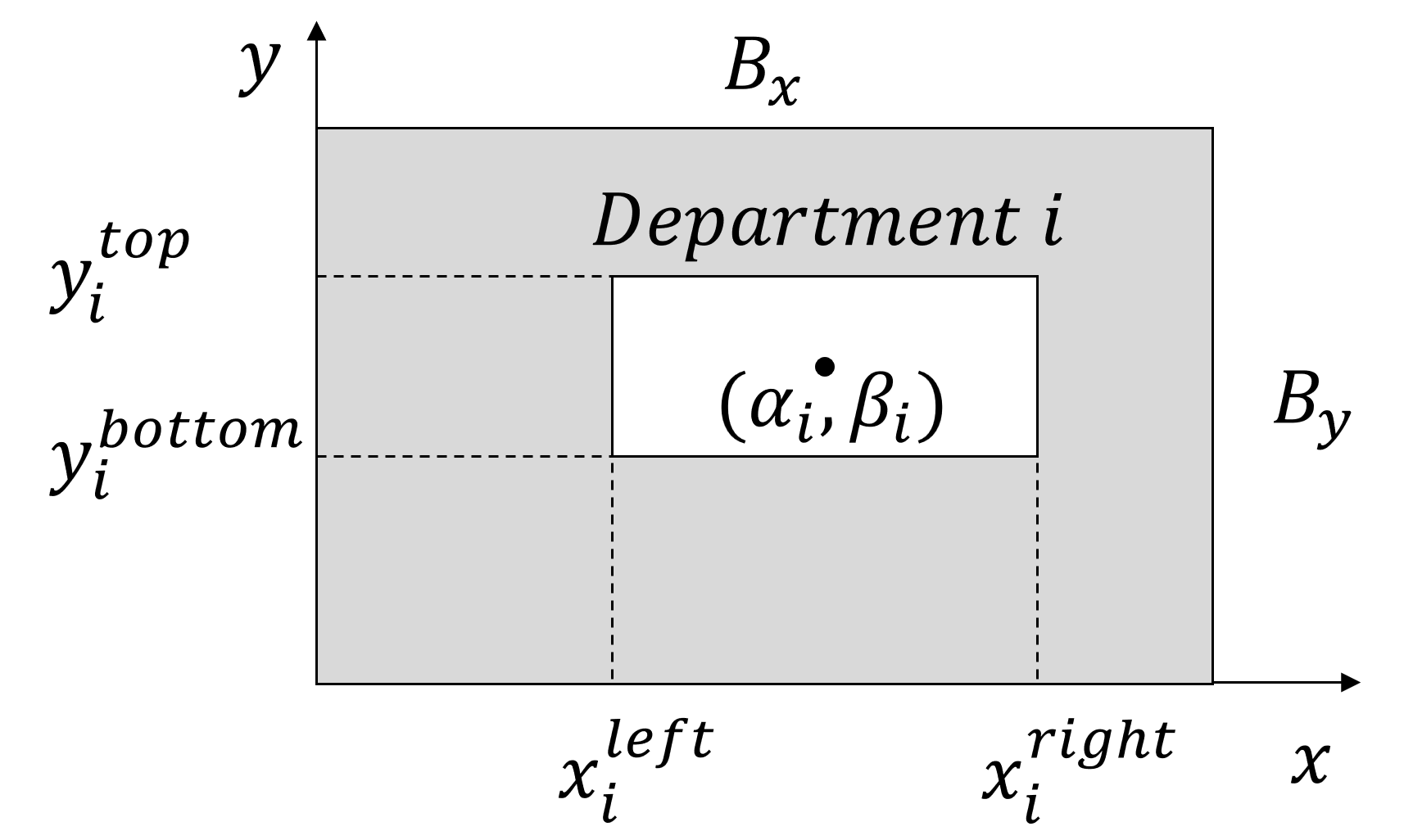
MIP as a two-dimensional packing model
The layout model is a 2D “packing” algorithm to determine the locations of rectangular objects with known shapes. Such a packing problem is also known as the “two-dimensional bin packing” problem.
Parameters
| Symbol | Description |
|---|---|
| \(m\) | number of departments |
| \(f_{ij}\) | flow from dept. \(i\) to dept. \(j\) (n. of unit loads moved per unit time) |
| \(c_{ij}\) | cost of moving a unit load one distance unit from dept. \(i\) to dept. \(j\) |
| \(B_x\) | building length (measured along the x-coordinate) |
| \(B_y\) | building width (measured along the y-coordinate) |
| \(A_i\) | area of dept. \(i\) |
| \(L_i^{\mathrm{LB}}\) | lower limit on the length of dept. \(i\) |
| \(L_i^{\mathrm{UB}}\) | upper limit on the length of dept. \(i\) |
| \(W_i^l\) | lower limit on the width of dept. \(i\) |
| \(W_i^{\mathrm{UB}}\) | upper limit on the width of dept. \(i\) |
| \(M\) | large number (if needed) |
Variables
| Symbol | Description |
|---|---|
| \(\alpha_i\) | x-coordinate of the centroid of dept. \(i\) |
| \(\beta_i\) | y-coordinate of the centroid of dept. \(i\) |
| \(x_i^{\mathrm{left}}\) | x-coordinate of the left (or west) side of dept. \(i\) |
| \(x_i^{\mathrm{right}}\) | x-coordinate of the right (or east) side of dept. \(i\) |
| \(y_i^{\mathrm{bottom}}\) | y-coordinate of the bottom (or south side) of dept. \(i\) |
| \(y_i^{\mathrm{top}}\) | y-coordinate of the top (or north side) of dept. \(i\) |
| \(z^{\mathrm{x}}_{ij}\) | 1 if dept. \(i\) is strictly to the east of dept. \(j\); 0 otherwise |
| \(z^{\mathrm{y}}_{ij}\) | 1 if dept. \(i\) is strictly to the north of dept. \(j\); 0 otherwise |
Variable relationships
Note that:
- Dept. \(i\) is strictly to the east of dept. \(j\) \(\iff\) \(x_j^{\mathrm{right}} \leq x_i^{\mathrm{left}}\).
- Dept. \(i\) is strictly to the north of dept. \(j\) \(\iff\) \(y_j^{\mathrm{top}} \leq y_i^{\mathrm{bottom}}\).
- Two departments are guaranteed not to overlap if they are “separated” along either the x-coordinate (i.e., 1) or y-coordinate (i.e., 2).
- Two departments can be separated along both the x- and y-coordinates.
Objective function
Minimize the cost per unit time for movement among the departments: the sum of rectilinear distances between departments \(d_{ij} = |\alpha_i - \alpha_j| + |\beta_i - \beta_j|\).
\[ \min \sum_{i}{\sum_{j}{f_{ij}c_{ij}(|\alpha_i - \alpha_j| + |\beta_i - \beta_j|)}} \]
Note that:
- Costs \(c_{ij}\) are implicitly assumed to be
- independent of the utilization of the handling equipment, and
- linearly related to the length of the move.
- If \(c_{ij}\) values do not satisfy (1) and (2), one may set \(c_{ij} = 1\) and focus only on total unit load travel in the facility (i.e., \(f_{ij}d_{ij}\)).
- \(c_{ij}\) may represent relative “weights” (based on unit load attributes such as size, weight, bulkiness, etc.) and minimize the weighted sum of unit load travel in the facility.
Constraints: Dimensions within bounds
The length and width of each department are within the specified bounds:
\[ \begin{align} L_i^{\mathrm{LB}} \leq (x_i^{\mathrm{right}} - x_i^{\mathrm{left}}) \leq L_{i}^{\mathrm{UB}} & \quad \text{for all} \; i \\ W_i^l \leq (y_i^{\mathrm{top}} - y_i^{\mathrm{bottom}}) \leq W_{i}^{\mathrm{UB}} & \quad \text{for all} \; i \\ \end{align} \]
Constraints: Area of department
The area requirement of each department:
\[ \begin{align} (x_i^{\mathrm{right}} - x_i^{\mathrm{left}})(y_i^{\mathrm{top}} - y_i^{\mathrm{bottom}}) = A_i & \quad \text{for all} \; i \end{align} \]
Strictly, the area constraint is a nonlinear (bilinear) constraint. Solvers such as Gurobi can handle such constraints directly (as a MIQCP problem), but they may be difficult to solve. We will show later how to linearize this constraint.
Constraints: Proper department sizes
Department sides are defined properly and located within the building in the x and y directions:
\[ \begin{align} 0 \leq x_i^{\mathrm{left}} \leq x_i^{\mathrm{right}} \leq B_x & \quad \text{for all} \; i \\ 0 \leq y_i^{\mathrm{bottom}} \leq y_i^{\mathrm{top}} \leq B_y & \quad \text{for all} \; i \\ \end{align} \]
Constraints: Centroid coordinates
Define the centroid of each department based on x and y coordinates.
\[ \begin{align} \alpha_i = 0.5x_i^{\mathrm{left}} + 0.5x_i^{\mathrm{right}} & \quad \text{for all} \; i \\ \beta_i = 0.5y_i^{\mathrm{bottom}} + 0.5y_i^{\mathrm{top}} & \quad \text{for all} \; i \\ \end{align} \]
Constraints: Non-overlapping departments
The department \(i\) is strictly to the east of department \(j\) if \(z_{ij}^{\mathrm{x}}=1\):
\[ \begin{align} x_j^{\mathrm{right}} \leq x_i^{\mathrm{left}} + M(1- z_{ij}^{\mathrm{x}}) & \quad \text{for all} \; i \; \text{and} \; j,\; i \neq j \end{align} \]
The department \(i\) is strictly to the north of department \(j\) if \(z_{ij}^{\mathrm{y}}=1\):
\[ \begin{align} y_j^{\mathrm{top}} \leq y_i^{\mathrm{bottom}} + M(1- z_{ij}^{\mathrm{y}}) & \quad \text{for all} \; i \; \text{and} \; j,\; i \neq j \end{align} \]
Departments are separated at least in the east–west or north–south direction:
\[ \begin{align} z_{ij}^{\mathrm{x}} + z_{ji}^{\mathrm{x}} + z_{ij}^{\mathrm{y}} + z_{ji}^{\mathrm{y}} \geq 1 & \quad \text{for all} \; i \; \text{and} \; j,\; i \leq j \end{align} \]
Non-overlap with indicator constraints
Indicator Constraints
The non-overlapping constraints model conditional statements (i.e., “if-then” statements): if \(z_{ij}^{\mathrm{x}}=1\), then \(x_j^{\mathrm{right}} \leq x_i^{\mathrm{left}}\). Similarly, if \(z_{ij}^{\mathrm{y}}=1\), then \(y_j^{\mathrm{top}} \leq y_i^{\mathrm{bottom}}\). These constraints ensure that departments do not overlap by enforcing separation along either the x- or y-coordinates.
If supported by the solver, you can use indicator constraints to model the relationships more compactly instead of using the big-M method. For example, the east–west separation constraint can be written as:
\[ \begin{align} z_{ij}^{\mathrm{x}}=1 \implies x_j^{\mathrm{right}} \leq x_i^{\mathrm{left}} & \quad \text{for all} \; i \; \text{and} \; j,\; i \neq j \end{align} \]
And similarly for the north–south direction. Using indicator constraints avoids the need for a large \(M\) and can improve numerical stability.
Constraints: Non-negativity and variables
\[ \begin{align} \alpha_i, \beta_i \geq 0 & \quad \text{for all} \; i \\ x_i^{\mathrm{left}}, x_i^{\mathrm{right}}, y_i^{\mathrm{bottom}}, y_i^{\mathrm{top}} \geq 0 & \quad \text{for all} \; i \\ z_{ij}^{\mathrm{x}}, z_{ij}^{\mathrm{y}} \in \{0,1\} & \quad \text{for all} \; i \; \text{and} \; j,\; i \neq j \end{align} \]
Linearizing the absolute values
If \(f_{ij} \geq 0 \; \forall i,j\), the absolute value can be removed by introducing a positive part and negative part for each term:
\[ \alpha_i - \alpha_j = \alpha_{ij}^+ - \alpha_{ij}^- \quad \text{such that} \quad |\alpha_i - \alpha_j| = \alpha_{ij}^+ + \alpha_{ij}^- \\ \beta_i - \beta_j = \beta_{ij}^+ - \beta_{ij}^- \quad \text{such that} \quad |\beta_i - \beta_j| = \beta_{ij}^+ + \beta_{ij}^- \]
where \(\alpha_{ij}^+\), \(\alpha_{ij}^-\), \(\beta_{ij}^+\), and \(\beta_{ij}^-\) are all nonnegative variables.
Then, you can rewrite distances \(d_{ij}\) in the objective function:
\[ d_{ij} = (|\alpha_i - \alpha_j| + |\beta_i - \beta_j|) = (\alpha_{ij}^+ + \alpha_{ij}^- + \beta_{ij}^+ + \beta_{ij}^-) \]
Strictly, \(|x| \leq x^+ + x^-\), but high values of \(x^+\) and \(x^-\) will hurt the objective function (when minimizing and assuming \(f_{ij} \geq 0\)). Thus, the solver will force either value to zero.
Linearizing the area constraints
The department area can be controlled through its perimeter (which is a linear function of the length and width of the department).
Consider:
\[ \begin{align} P_i ^{\mathrm{LB}} & = \quad \text{lower bound on perimeter of department} \, i\\ P_i ^{\mathrm{UB}} & = \quad \text{upper bound on perimeter of department} \, i\\ \end{align} \]
and add the constraint:
\[ \begin{align} P_i^{\mathrm{LB}} \leq 2(x_i^{\mathrm{right}} - x_i^{\mathrm{left}} + y_i^{\mathrm{top}} − y_i^{\mathrm{bottom}})≤ P_i^{\mathrm{UB}} & \quad \text{for all} \; i \end{align} \]
The area to perimeter conversion is an approximation; note that an area can result in different perimeters.
Area flexibility
Retaining some flexibility in departmental area requirements reduces the likelihood of having no feasible solutions when obstacles and/or fixed departments are present.
Example
Consider a 10x10 building and four departments with the following area requirements: A1 = 18, A2 = 20, A3 = 27, and A4 = 33 (note that 18+20+27+33= 98). Without flexible areas, fixing A2 at the northeast corner leads to infeasibility.
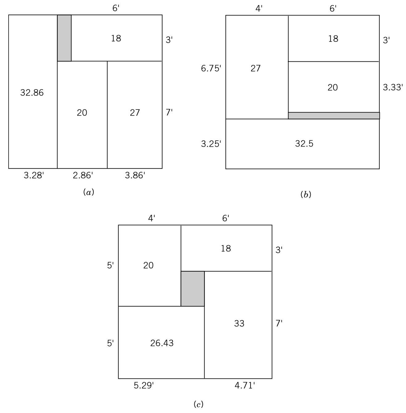
Inserting clearances between departments
To capture an “X” relationship between two departments \(i\) and \(j\), one can also insert a minimum required distance (clearance) between them.
If department \(i\) is strictly to the east of department \(j\), then \(i\) and \(j\) are separated by a minimum distance \(\Delta_{ij}^{\mathrm{x}}\) along their x-coordinates:
\[ \begin{align} x_j^{\mathrm{right}} + \Delta_{ij}^{\mathrm{x}} \leq x_i^{\mathrm{left}} + M(1- z_{ij}^{\mathrm{x}}) & \quad \text{for all} \; i \; \text{and} \; j,\; i \neq j \end{align} \]
If department \(i\) is strictly to the north of department \(j\), then \(i\) and \(j\) are separated by a minimum distance \(\Delta_{ij}^{\mathrm{y}}\) along their y-coordinates:
\[ \begin{align} y_j^{\mathrm{top}} + \Delta_{ij}^{\mathrm{y}} \leq y_i^{\mathrm{bottom}} + M(1- z_{ij}^{\mathrm{y}}) & \quad \text{for all} \; i \; \text{and} \; j,\; i \neq j \end{align} \]
Clearances should be used sparingly; they limit the number of feasible solutions.
Controlling the shape of departments
Place an upper limit on the ratio (\(R_i \geq 1\)) of department \(i\)’s longer side to its shorter side:
\[ \begin{align} (x_i^{\mathrm{right}} - x_i^{\mathrm{left}}) \leq R_i(y_i^{\mathrm{top}} - y_i^{\mathrm{bottom}}) & \quad \text{for all} \; i \\ (y_i^{\mathrm{top}} - y_i^{\mathrm{bottom}}) \leq R_i(x_i^{\mathrm{right}} - x_i^{\mathrm{left}}) & \quad \text{for all} \; i \\ \end{align} \]
Depending on which side is the longer, at most one (i.e., could be none) of the above constraints will be “binding” (i.e., hold as an equality for non-square departments).
Caveats
- If too complex, terminate the branch-and-bound search when the gap (i.e., the difference between the least lower bound and the incumbent solution) is within a certain bound (e.g., 5–10%).
- Determine the north–south and east–west relationships between the departments (i.e., \(z_{ij}^{\mathrm{y}}\) and \(z_{ij}^{\mathrm{y}}\) variables) a priori by constructing a “design skeleton.” Then, the MIP model will only “pack” the departments within the building.
- There are cases where L-shaped or U-shaped departments may be more appropriate or necessary.
- The MIP model may also be used to improve a given layout (i.e., find the locations of non-fixed departments) after specifying the known dimensions and location of fixed departments and/or obstacles (i.e., \(x_i^{\mathrm{left}}\), \(x_i^{\mathrm{right}}\), \(y_i^{\mathrm{bottom}}\), \(y_i^{\mathrm{top}}\), \(\alpha_i\), and \(\beta_i\)).
- Non-rectangular obstacles may be represented as a collection of rectangular dummy departments.
References
Warehousing - M-IEM - Breno A. Beirigo